PicBasic PRO Examples
These examples are designed to demonstrate how to use a PIC16F877 and PicBasic PRO to communicate with our modules, most of these examples use the LCD03 display module to show the results. All the modules which use the I2C bus have 1k8 pull-up resistors to 5v. You only need one set of resistors for the whole I2C bus regardless of however many I2C devices you have connected to it. You can find more information about the I2C bus in our I2C tutorial.
Note - Pin 1 of the PIC16F877 is MCLR. When your programmer is not connected to this pin, it should be pulled to +5v with a resistor. Any value from 1k to 47k should be fine. You may need disconnect it when the programmer is connected.
| Index: | |
| CMPS03 | Magnetic Compass |
| SRF01 | Ultrasonic Ranger |
| SRF02 | Ultrasonic Ranger |
| SRF04 | Ultrasonic Ranger |
| SRF05 | Ultrasonic Ranger |
| SRF08 | Ultrasonic Ranger |
| SRF10 | Ultrasonic Ranger |
| SRF235 | Ultrasonic Ranger |
| TPA81 | 8 Pixel Thermal Sensor |
| SD20 | Servo Controller |
| SD21 | Servo Controller |
| MD03 | 24V 20A Motor Driver |
| MD22 | Dual 24V 5A Motor Driver |
| MD25 | RD02 Motor Driver |
| RLY08 | Relay Module |
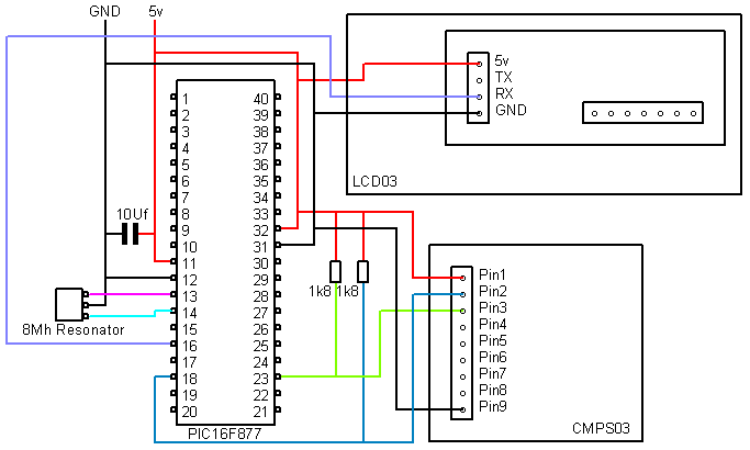
CMPS03 Magnetic Compass
This uses the I2C bus to connect the PIC16F877 to the CMPS03. It reads the
bearing as a 16 bit integer and displays the bearing as a number
0.0-359.9 on the LCD03.
| Download the CMPS03PicBasic.PBP file |
SRF01 Ultrasonic Ranger
The SRF01 uses a single pin for both serial input and output. You can have up to
16 SRF01's connected to a single pin. The Range is displayed on an LCD03 module.
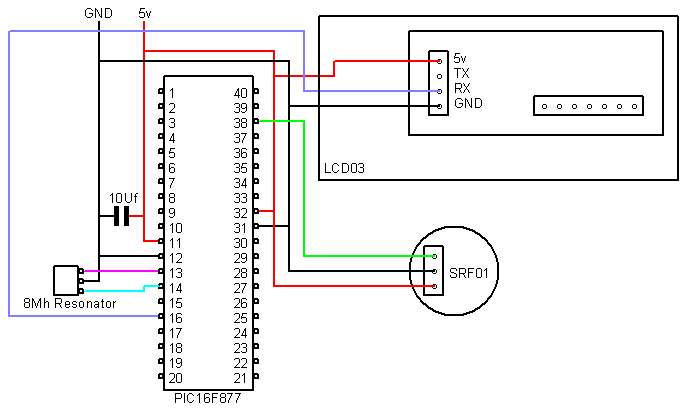
| Download the SRF01PicBasic.PBP file |
SRF02, SRF08, SRF10,
SRF235 Ultrasonic Rangers
The SRF02, SRF08, SRF10 and SRF235 all use the same I2C interface. The
basic ranging commands are the same, so this example works for all these
rangers.
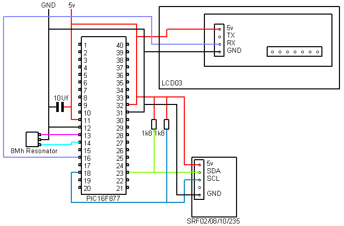
| Download the srf02PicBasic.PBP file |
SRF04 Ultrasonic Ranger
As the SRF04 and SRF05 use the same method of communicating this example is compatible
with both the SRF04 and SRF05.
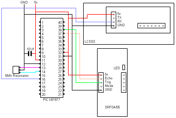
| Download the SRF04PicBasic.PBP file |
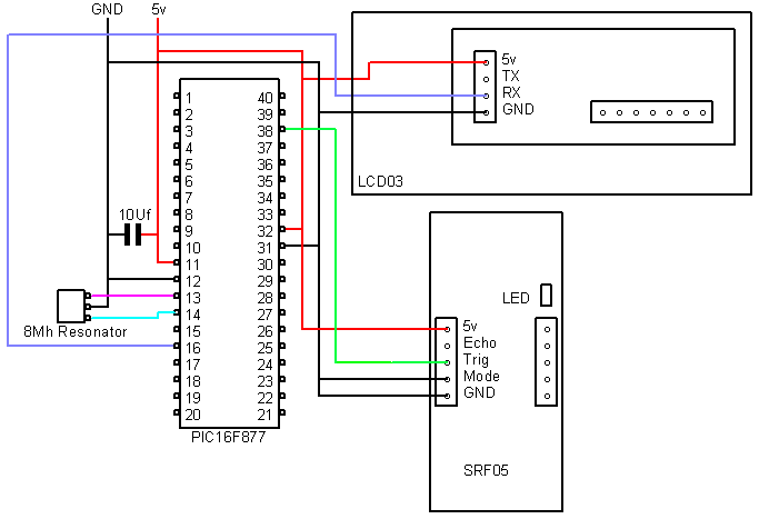
SRF05 Ultrasonic Ranger
This example uses the SRF05 in one pin mode, where the Trigger and Echo signals
appear on the same pin. Note the SRF05's mode pin is connected to ground to
place it in one pin mode.
|
Download the SRF05PicBasic.PBP file |
SRF08 Ultrasonic Ranger
Although the SRF08 is compatible with the SRF02 example, this example uses the SRF08 to take range and light
readings and displays them on the LCD03.

|
Download the SRF08PicBasic.PBP file |
TPA81 Thermal Sensor
The TPA81 connects to the PIC16F877 using the I2C bus. This example displays the
ambient temperature and 8 temperatures from thermal sensor, on an LCD03 module
and drives a servo.
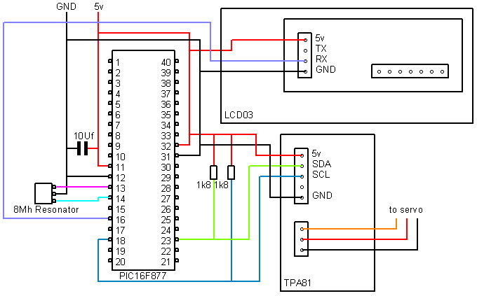
| Download the TPA81PicBasic.PBP file |
SD20 Servo Controller
This example shows how to drive a servo by using
the SD20 chip, you can control up to 20 servo's.

| Download the SD20PicBasic.PBP file |
SD21 Servo Controller
The SD21 is a ready wired module which can save a lot of time compared to the
SD20 above. This example moves all servos through their maximum range.
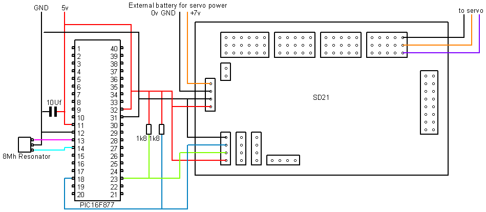
| Download the SD21PicBasic.PBP file |
MD03 24V 20A Motor Driver
This example runs the motor forwards and backwards, displaying the
temperature and motor current on the LCD03.
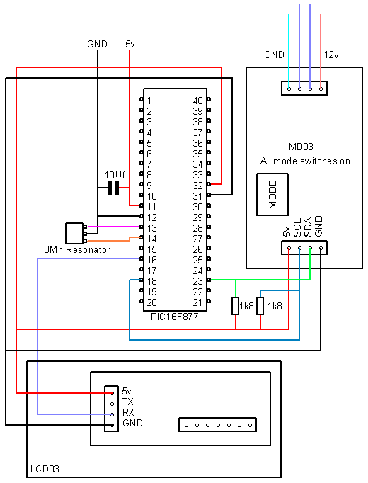
| Download the MD03PicBasic.PBP file |
MD22 24V 5A Motor
Driver
This example runs the motors forwards and backwards.

| Download the MD22PicBasic.PBP file |
MD25 RD02 Motor
Controller
This example drives the RD02 motors and displays the encoder values on the LCD03
in hex format, as well as the battery
voltage. It runs the motors back and forth between 2 values output by the
encoders.
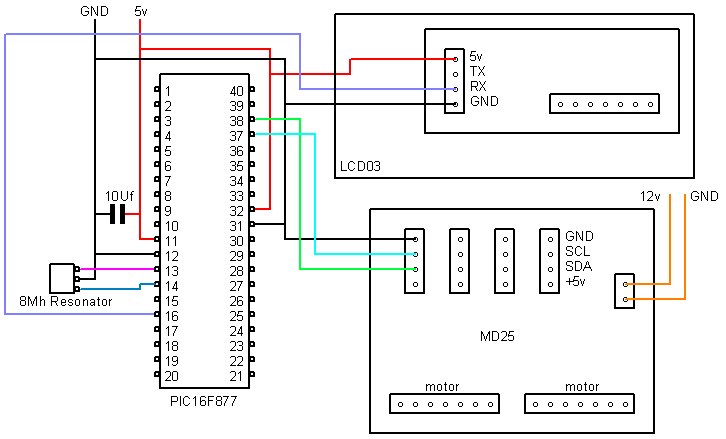
| Download the MD25PicBasic.PBP file |
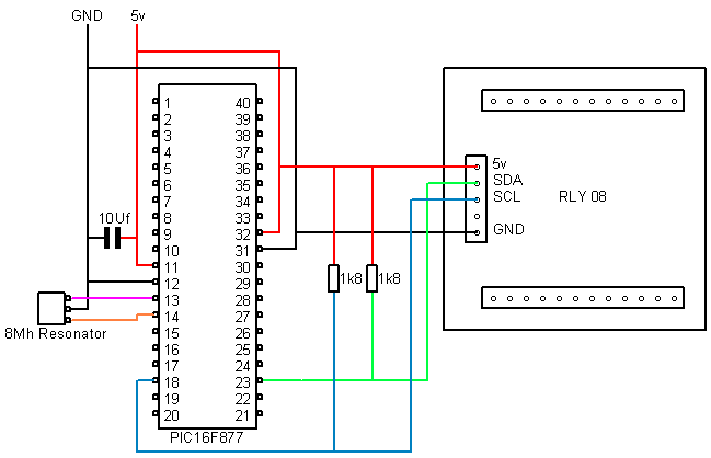
RLY08 Relay Module
Example of switching all the relays on and then off, and then turning them on
and off individually.
| Download the RLY08PicBasic.PBP file |