Connecting Multiple SRF08 Sonar Modules to the BS2
Introduction
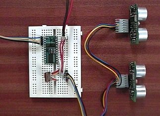
The SRF08 modules use the I2C bus for
communication. This example shows how to connect two SRF08's to the BS2,
however it is expandable to up 16 SRF08's on the I2C bus. The SDA (data) and SCL (clock) lines are connected to
pins P8 and P9 on the BS2. These are the pins used by the BS2p for the I2CIN and
I2COUT commands.
If you are using BS2p firmware release Rev C or later, then you can use the I2CIN and I2COUT commands to control the SRF08's. Example.
The example below should be used for earlier revisions of the
BS2p as well as the BS2, BS2e and BS2sx. This example uses a combination of bit
bashing and the SHIFTIN and SHIFTOUT commands. It has been tested with the BS2
and BS2p.
The BS2 internal 5v regulator is not suitable for powering much external
circuitry. I therefore recommend you use a separate 5v regulator.
Circuit Schematic for connecting two SRF08 Sonar Modules to the Basic Stamp BS2
The schematic above shows 4k7 pull-up resistors on the SCL and SDA lines to
Vdd, as recommended by Parallax.
For greater noise immunity, I recommend pulling up to the SRF08's 5v supply
instead (so as not to place any more load on the BS2) and using 1k8 resistors.
Changing the SRF08 I2C Address
Before you can use the SRF08's you will need to re-program their I2C
addresses from the default address of 0xE0 they are supplied with. The simple
program below will do this. Make sure you only have one SRF08 connected when you
do this. You only have to change the NEW_SRF08_ADDRESS constant in the program below to the address you want. For
example if you want the SRF08 to be at hex address 0xF2, then change
NEW_SRF08_ADDRESS to
read;
NEW_SRF08_ADDRESS con
$f2 ' Place new address
for SRF08 here
Now download the program to the BS2, you will see rapid brief flashes on the
Red Led on the SRF08 indicating that the change of address was successful. It is
wise to make a note of the new address on the SRF08 itself.
To use the example
code described later on this page, set one SRF08 to address 0xE0 and the other
to 0xE2. The following program can be downloaded here.
| '{$STAMP BS2}
'*********************************************************** NEW_SRF08_ADDRESS con
$e2 ' Place new
address for SRF08 here SCL con
9
' I2C clock loop var
byte
' just a looping counter I2cAddr =
0
' use general broadcast address ($00) if don't know current SRF08 address endlessloop: '-------------------------------------------------------------------------------------------- I2cByteWrite:
' writes I2cData.lowbyte to I2cReg at I2cAddr I2cWordWrite:
' writes I2cData to I2cReg at I2cAddr I2cOutByte: I2cInByte: I2cStart
' I2C start bit sequence I2cStop:
' I2C stop bit sequence |
Displaying Light Sensor and Range readings in a PC Debug window
Now that you have your SRF08's re-programmed to their new I2C addresses
(0xE0 and 0xE2) the following sample code will display the light sensor
reading and the 1st range reading, for each SRF08 in a Debug window on the PC
.
The sample code below can be downloaded here.
| '{$STAMP BS2}
'*********************************************************** loop var
byte
' just a looping counter ' 2nd SRF08 Ranger goto main '-------------------------------------------------------------------------------------------- I2cByteWrite:
' writes I2cData.lowbyte to I2cReg at I2cAddr I2cWordWrite:
' writes I2cData to I2cReg at I2cAddr I2CByteRead: I2CWordRead: I2cOutByte: I2cInByte: I2cStart
' I2C start bit sequence I2cStop:
' I2C stop bit sequence |