Rx
Tx
Mode
GND
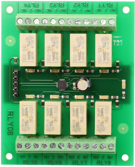
RLY08 - 8
Relay Outputs
Technical Documentation
Serial Mode
For I2C mode click
here
Connections
|
+5v Rx Tx Mode GND |
|
Serial mode selection
Serial Mode is selected by connecting the Mode pin to ground. The Tx
pin is out of the RLY08 and should be connected to Rx on your controller. The Rx
pin is into the RLY08 and should be connected to Tx on your controller. These
signals are 5v levels, not RS232. Do NOT connect RS232 directly to the module - you
will destroy it. Use a MAX232 or equivalent to convert the RS232 levels to 5v.
Communication settings
The Serial mode operates over a link with a baud rate of 9600 bps (no parity,
1 stop bit) and 5v signals, The RLY08 can be found at a factory default address of 1, although this is
easily changed to another of eight locations - see Changing the RLY08 Address
.
Commands
To send a command to the RLY08, you need to send two bytes. The first is the
RLY08's address 1 (default) to 8, and then the actual command
itself - see below. The RLY08 will then carry out the command and if applicable send its response. The only exception to this being the "Set relay
states" command, it requires an additional required states byte to be
sent immediately after the command byte. This will then set all relays to the
status of the equivalent bit within the byte, with a high bit powering the relay
on and a low bit turning it off.
Commands for Serial
| Command |
Action |
|
| dec | hex | |
| 90 | 5A | Get software version - transmits a single byte back to the controller containing the software revision |
| 91 | 5B |
Get relay states - transmits a single byte back to the controller, bit high meaning the corresponding relay is powered |
| 92 | 5C | Set relay states - the next byte sent to the command register will set all relay states, All on = 255 (11111111) All off = 0 |
| 100 | 64 | All relays on |
| 101 | 65 | Turn relay 1 on |
| 102 | 66 | Turn relay 2 on |
| 103 | 67 | Turn relay 3 on |
| 104 | 68 | Turn relay 4 on |
| 105 | 69 | Turn relay 5 on |
| 106 | 6A | Turn relay 6 on |
| 107 | 6B | Turn relay 7 on |
| 108 | 6C | Turn relay 8 on |
| 110 | 6E | All relays off |
| 111 | 6F | Turn relay 1 off |
| 112 | 70 | Turn relay 2 off |
| 113 | 71 | Turn relay 3 off |
| 114 | 72 | Turn relay 4 off |
| 115 | 73 | Turn relay 5 off |
| 116 | 74 | Turn relay 6 off |
| 117 | 75 | Turn relay 7 off |
| 118 | 76 | Turn relay 8 off |
| 160 | A0 | 1st byte in sequence to change serial address |
| 165 | A5 | 3rd byte in sequence to change serial address |
| 170 | AA | 2nd byte in sequence to change serial address |
Changing the RLY08 Address
To change the address of the RLY08 you must have only one module connected.
Write the 3 sequence commands in the correct order followed by the address. For
example; to change the address of a RLY08 currently at 1 (the default shipped
address) to 5, write the following to address 1; (0xA0, 0xAA, 0xA5, 0x05 ).
These commands must be sent in the correct sequence to change the address,
additionally, No other command may be issued in the middle of the sequence. The
sequence must be sent as four separate commands to the current address of the
module. i.e. 0x01, 0xA0 then 0x01, 0xAA, then 0x01, 0xA5 and finally 0x01, 0x05.
When done, you should label the module with its new address, however if you do
forget, just power it up without sending any commands. The RLY08 will flash its
address out on the LED. One long flash followed by a number of shorter flashes
indicating its address. The flashing is terminated immediately on sending a
command the RLY08.
| Address | Long Flash | Short flashes | |
| Decimal | Hex | ||
| 1 | 01 | 1 | 0 |
| 2 | 02 | 1 | 1 |
| 3 | 03 | 1 | 2 |
| 4 | 04 | 1 | 3 |
| 5 | 05 | 1 | 4 |
| 6 | 06 | 1 | 5 |
| 7 | 07 | 1 | 6 |
| 8 | 08 | 1 | 7 |
Take care not to set more than one module to the same address, there will be a bus collision and very unpredictable results.