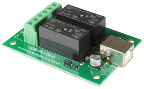
USB-RLY02
- 2 relay outputs at 16A
Technical Documentation
Overview
The USB-RLY02 provides two volt free contact relay outputs with a current
rating of up to 16Amp each. The USB-RLY02 is powered and instructed from any standard USB bus
and does not require any additional power. The relays are SPCO (Single Pole Change Over) types. The normally
open, normally closed and common pins are all available on the screw terminals.
Operating Temperature
-40C to +70C
LED indication A full datasheet for the relays used on the USB-RLY02 is here: HF115F datasheet First Step - Install the Driver Which COM port? Commands Action Get relay states - sends a
single byte back to the controller, bit high meaning the corresponding relay is
powered Board dimensions Test program
The USB-RLY02 provides a red LED mounted immediately next to each relay to
indicate whether it is in a powered state (LED on).
Relay power rating
load type
Typical applications
Rating
AC1
Non inductive or
slightly inductive loads 16A @ 250V AC
AC15
Control of
electromagnetic load
(>72VA) 3A @ 120V AC
1.5A @ 240V AC
AC3
Control of motor
750W
DC1
Non inductive or
slightly inductive loads 16A @ 24V DC
DC13
Control of electromagnetic
loads 0.22A @ 120V DC
0.1A @ 250V DC
The USB-RLY02 module uses the Microchip PIC18F14K50 to handle all the USB protocols.
Before using the USB-RLY02,
you will need to download the Devantech
inf files and unzip them into a temporary folder. Connect the USB-RLY02 and
windows will detect it and ask for the drivers. Point windows to the inf folder
and it will install the driver. The RLY02 will now appear as a com port.
After installing the drivers, and plugging in the USB-RLY02 module to a spare
USB port, you will want to know which COM port it has been assigned to. This
will vary from system to system depending on how many COM ports you currently
have installed. To find out where it is, right click on your "My
Computer" desktop icon and select the "Device Manager" tab. Now
scroll down and open the "Ports (COM & LPT)" tab. You should see
the USB serial port listed - COM2 in the example below. If you want to change
the COM port number - just right click on it, select properties, select advanced
and select the COM port number from the available list. The COM port may be left
at the default baud rate etc, because they are not actually used - there is a
direct USB connection into the processor. 
The USB-RLY02 operates with an easy to use command set as described in the table
below. Most commands are only a single byte and if applicable the USB-RLY02 will automatically
send its response. The only exception to this being the "Set relay
states" command which requires and additional desired states byte to be
sent immediately after the command byte.
Command
dec
hex
90
5A
Get software version - returns 2 bytes, the
first being the Module ID which is 10, followed by the software
version
91
5B
92
5C
Set relay states -
the next single byte will set all relays states, All on = 3 (xxxxxx11)
All off = 0
100
64
All relays on
101
65
Turn relay 1 on
102
66
Turn relay 2 on
110
6E
All relays
off
111
6F
Turn relay 1 off
112
70
Turn relay 2 off

To get the USB-RLY02 up and running in the minimum amount of
time we have put together a RelayTest program to demonstrate the functionality of
the module. 