USB-I2C Interface Guide
Overview
To aid in the evaluation and testing of I2C modules with our
USB-I2C device we have written a program to allow rapid setup. The program offers the ability to read and write to
devices with single byte internal address registers, dual byte address registers
or no internal register set.
The File menu
This menu contains the standard options of 'New', 'Open', 'Save as' and 'Exit'. The
program offers the option to save and recall defined register sets by saving a
file with an extension of .i2c. We have included some of the register sets of
our modules in the projects directory, a click of the 'Open'
option should present these files immediately.
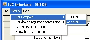
Setup menu
'Set response bytes' (device with no internal registers) - allows the user to
specify the bytes that are returned following a read of the device.
'Show byte sequences' - When enabled a list box will be displayed showing
the byte sequences currently being used for communication with the module.
Module address and read registers
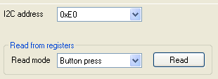
Once we have setup the register set and defined the comport from the
setup menu we can now select our I2C address. This is done with the use of the combo box
which provides a drop down selectable list of all 127 possible addresses.
Please note that addresses are in their full 8 bit format, some devices
such as the Arduino don't include the read bit in the address, it's easy to
convert though by just multiplying the 7 bit address by 2.
A read of data can now be performed with a click of the read button, or you may elect to set continuous read which
provides the option of reading every 100ms, 200ms, 500ms, 1s or 2s. Please
note that I do not recommend setting the continuous read mode for large
register sets such as EEPROM's which can have up to 65536 different
registers. The program will spend all of its time continually reading the
registers in that event.
Register display and writing data
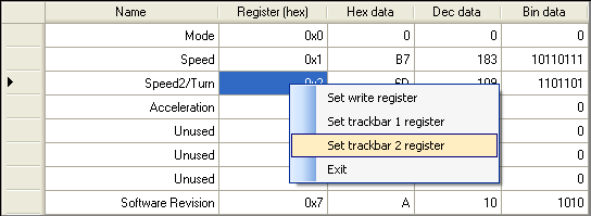
If the target device has no internal address register then the read data display will be similar to this example but will require you to select 'Set response bytes' to add rows. The register column will also change to 'Response' and the rows will be numbered in decimal.
A read of the target device data requires that we have set the i2c address of the module, defined the internal address register size and also the comport where the USB-I2C adaptor resides.
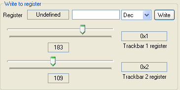
Writing data to the target device is done by right clicking the mouse on the register number you wish to Allocate. This will bring up a menu allowing you to select whether you wish to assign a register to a track bar or the textbox. If the register is assigned to 'Set write register' then you can write data in decimal, hexadecimal, binary or ascii using the text box for data and the combo box for format. If a register is assigned to 'Set trackbar x register', then writes to the register will occur as soon as the track bar value changes.
Deleting a register from the setup is just a matter of clicking the row start (the column with the arrowhead in) and pressing the delete key, multiple row deletion is also permitted by selecting multiple rows.
Byte sequences
The program provides the option to display the bytes it is using in
order to retrieve or write data. If the module is in one of the register
set modes then it will also display the start and end address of the
registers. It is worth remembering that the USB-I2C supports maximum frame sizes of
64 bytes for a read and the registers may not necessarily be contiguous
for your setup,
thus the start and end addresses for each grab of data make easier
reading.
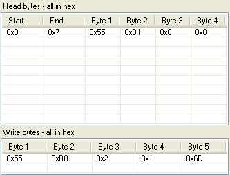
The list box above is the output from reading the full register set
of an MD22 (8 registers) so we start at address 0x0 and go up to address
0x7. Byte 1 contains 0x55 and tells the USB-I2C that we wish to use a single byte addressed device,
byte 2 is the address with the read bit
set, byte 3 is the start address of 0 and byte 4 is the number of data
bytes to read, in this case 8.
Following the write sequence we again have 0x55 for a single byte address
register module, then 0xB0 which is the I2C device with its read bit
clear (for a write), byte 3 is the start address of 0x02, byte 4 is the number of
sequential data bytes
to be written (always 1 for my program) and then finally byte 5 is the
data to be written, a random speed value of 0x6D.