SDA
SCL
Mode
GND
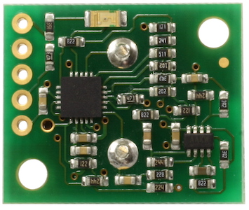
SRF02 Ultrasonic range finder
Technical Specification
I2C Mode
For Serial mode click here
I2C Communication
To use the SRF02 in I2C mode, make sure nothing is connected to the mode pin, it
must be left unconnected.
The
I2C bus is available on popular controllers such as the OOPic, Stamp
BS2p, PicAxe etc. as well as a wide variety of micro-controllers. To the programmer the
SRF02 behaves in the same way as the ubiquitous 24xx series EEPROM's, except
that the I2C address is different. The default shipped address of the SRF02 is
0xE0. It can be changed by the user to any of 16 addresses E0, E2, E4, E6, E8,
EA, EC, EE, F0, F2, F4, F6, F8, FA, FC or FE, therefore up to 16 sonar's can be
used.
Connections
The connections to the SRF02 are identical to the SRF08 and SRF10 rangers. The "Mode" pin should be left
unconnected, it has an internal pull-up resistor. The SCL and SDA lines should each have a
pull-up resistor to +5v somewhere on the I2C bus. You only need one pair of
resistors, not a pair for every module. They are normally located with the bus
master rather than the slaves. The SRF02 is always a slave - never a bus master.
If you need them, I recommend 1.8k resistors. Some modules such as the OOPic
already have pull-up resistors and you do not need to add any more.
|
+5v SDA SCL Mode GND |
|
Registers
The SRF02 appears as a set of 6 registers.
|
Location |
Read |
Write |
|
0 |
Software Revision |
Command Register |
|
1 |
Unused (reads 0x80) |
N/A |
|
2 |
Range High Byte |
N/A |
|
3 |
Range Low Byte |
N/A |
| 4 | Autotune Minimum - High Byte | N/A |
| 5 | Autotune Minimum - Low Byte | N/A |
Only location 0 can be written to. Location 0 is the command register and is used to start a ranging session. It cannot be read. Reading from location 0 returns the SRF02 software revision. The ranging lasts up to 65mS, and the SRF02 will not respond to commands on the I2C bus whilst it is ranging.
Locations, 2 and 3, are the 16bit unsigned result from the latest ranging - high byte first. The meaning of this value depends on the command used, and is either the range in inches, or the range in cm or the flight time in uS. A value of 0 indicates that no objects were detected. Do not initiate a ranging faster than every 65mS to give the previous burst time to fade away.
Locations, 4 and 5, are the 16bit unsigned minimum range. This is the approximate closest range the sonar can measure to. See the Autotune section below for full details.
Commands
The are three commands to initiate a ranging (80 to 82), to return the result in inches, centimeters or
microseconds. Another set of three commands (86 to 88) do the same, but without
transmitting the burst. These are used where the burst has been transmitted by
another sonar. It is up to you to synchronize the commands to the two sonar's. There
is a command (92) to transmit a burst without doing the ranging and also a set of commands to change
the I2C address.
| Command | Action | |
| Decimal | Hex | |
| 80 | 0x50 | Real Ranging Mode - Result in inches |
| 81 | 0x51 | Real Ranging Mode - Result in centimeters |
| 82 | 0x52 | Real Ranging Mode - Result in micro-seconds |
| 86 | 0x56 | Fake Ranging Mode - Result in inches |
| 87 | 0x57 | Fake Ranging Mode - Result in centimeters |
| 88 | 0x58 | Fake Ranging Mode - Result in micro-seconds |
| 92 | 0x5C | Transmit an 8 cycle 40khz burst - no ranging takes place |
| 96 | 0x60 | Force Autotune Restart - same as power-up. You can ignore this command. |
| 160 | 0xA0 | 1st in sequence to change I2C address |
| 165 | 0xA5 | 3rd in sequence to change I2C address |
| 170 | 0xAA | 2nd in sequence to change I2C address |
Ranging
To initiate a ranging, write one of the above commands to the
command register and wait the required amount of time for completion and read
the result. The echo buffer is cleared
at the start of each ranging. The ranging lasts up to 66mS, after this the range
can be read from locations 2 and 3.
Checking for Completion of Ranging
You do not have to use a timer on your own controller to wait for ranging to
finish. You can take advantage of the fact that the SRF02 will not respond to
any I2C activity whilst ranging. Therefore, if you try to read from the SRF02 (we use the software revision number a location 0) then you will get 255 (0xFF)
whilst ranging. This is because the I2C data line (SDA) is pulled high if
nothing is driving it. As soon as the ranging is complete the SRF02 will again
respond to the I2C bus, so just keep reading the register until its not 255
(0xFF) anymore. You can then read the sonar data. Your controller can take
advantage of this to perform other tasks while the SRF02 is ranging. The
SRF02 will always be ready 70mS after initiating the ranging.
LED
The red LED is used to flash out a code for the I2C address on power-up (see
below). It also gives a brief flash during the "ping" whilst ranging.
Changing the I2C Bus Address
To change the I2C address of the SRF02 you must have only one sonar on the bus.
Write the 3 sequence commands in the correct order followed by the address.
Example; to change the address of a sonar currently at 0xE0 (the default shipped
address) to 0xF2, write the following to address 0xE0; (0xA0, 0xAA, 0xA5, 0xF2
). These commands must be sent in the correct sequence to change the I2C
address, additionally, No other command may be issued in the middle of the
sequence. The sequence must be sent to the command register at location 0, which
means 4 separate write transactions on the I2C bus. When done, you should label the sonar with its address, however if you
do forget, just power it up without sending any commands. The SRF02 will flash
its address out on the LED. One long flash followed by a number of shorter
flashes indicating its address. The flashing is terminated immediately on
sending a command the SRF02.
| Address | Long Flash | Short flashes | |
| Decimal | Hex | ||
| 224 | E0 | 1 | 0 |
| 226 | E2 | 1 | 1 |
| 228 | E4 | 1 | 2 |
| 230 | E6 | 1 | 3 |
| 232 | E8 | 1 | 4 |
| 234 | EA | 1 | 5 |
| 236 | EC | 1 | 6 |
| 238 | EE | 1 | 7 |
| 240 | F0 | 1 | 8 |
| 242 | F2 | 1 | 9 |
| 244 | F4 | 1 | 10 |
| 246 | F6 | 1 | 11 |
| 248 | F8 | 1 | 12 |
| 250 | FA | 1 | 13 |
| 252 | FC | 1 | 14 |
| 254 | FE | 1 | 15 |
Take care not to set more than one sonar to the same address, there will be a bus collision and very unpredictable results.
Note - there is only one module address stored in the SRF02. If
you change it, the equivalent Serial Mode address will also change:
0xE0, 0xE2, 0xE4, 0xE6, 0xE8, 0xEA, 0xEC, 0xEE, 0xF0,
0xF2, 0xF4, 0xF6, 0xF8, 0xFA, 0xFC, 0xFE I2C addresses
0x00, 0x01, 0x02, 0x03, 0x04, 0x05, 0x06, 0x07, 0x08,
0x09, 0x0A, 0x0B, 0x0C, 0x0D, 0x0E, 0x0F Equivalent Serial addresses
AutoTune
The SRF02 does not require any user calibration. You power up and go right ahead
and use the SRF02.
Internally, there are tuning cycles happening automatically in the background.
After the ultrasonic burst has been transmitted, the transducer keeps on ringing
for a period of time. It is this ringing which limits the closest range the
SRF02 can measure, this is normally 20cm of non-detection. The SRF02 is able to detect the
transducer ring time and move its detection threshold right up to it, giving the
SRF02 the very best performance possible. On power up, the detection threshold
is set to 28cm (11"). The tuning algorithms quickly back this right up to
the transducer ring. This happens within 5-6 ranging cycles - less than half a
second at full scan speed. After this the tuning algorithms continue to monitor
the transducer, backing the threshold up even further when possible or easing it
out a bit when necessary. The tuning algorithms work automatically, in the
background and with no impact on scan time.
The minimum range can be checked, if required by reading registers 4 and 5. This
value is returned in uS, cm or inches, the same as the range. It is also
possible to make the SRF02 re-tune by writing command 96 but you can ignore this
command. It is used during our testing.