SDA
SCL
Mode
GND
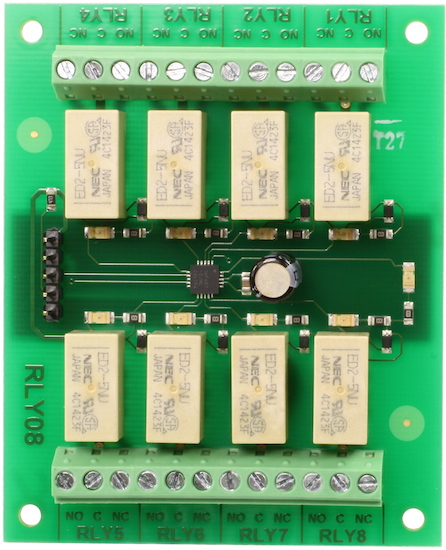
RLY08 - 8
Relay Outputs
Technical Documentation
I2C mode
For serial mode click
here
Connections
|
+5v SDA SCL Mode GND |
|
I2C Mode selection
I2C operation is activated when the mode pin is left open circuit.
I2C Operation
I2C
Bus
The RLY08 is located on the I2C bus at a factory default address of
0X70. The SCL and SDA lines should have pull-up resistors on them somewhere
on the bus. You only require 1 pair of resistors for the whole I2C bus, not
specifically for the RLY08. They are normally on the master controller and you
may already have them. If not, anything between 1k8 and 10k should work. I
recommend 1k8 for best noise immunity.
RLY08 register set
The RLY08 has only
two registers, register 0 and acts as a dual purpose
register. When written to it is the command register where all of the instructions
from the commands section should be sent. When read it returns the software
version.
Register 1 is the relay register, when written to it allows the
user to change all eight relay positions at once with a single byte.
When the register is read it provides the current positions of the relays. If
all relays are powered the register would contain 255 (1111 1111), all relays in
the un-powered state would result in 0 (0000 0000)
I2C register set
| register |
Read |
Write |
| 0 | Software version | Command register |
| 1 | Relay states | Relay states |
Commands for I2C
| decimal | hex |
command |
| 100 | 0x64 | All relays on |
| 101 | 0x65 | Turn relay 1 on |
| 102 | 0x66 | Turn relay 2 on |
| 103 | 0x67 | Turn relay 3 on |
| 104 | 0x68 | Turn relay 4 on |
| 105 | 0x69 | Turn relay 5 on |
| 106 | 0x6A | Turn relay 6 on |
| 107 | 0x6B | Turn relay 7 on |
| 108 | 0x6C | Turn relay 8 on |
| 110 | 0x6E | All relays off |
| 111 | 0x6F | Turn relay 1 off |
| 112 | 0x70 | Turn relay 2 off |
| 113 | 0x71 | Turn relay 3 off |
| 114 | 0x72 | Turn relay 4 off |
| 115 | 0x73 | Turn relay 5 off |
| 116 | 0x74 | Turn relay 6 off |
| 117 | 0x75 | Turn relay 7 off |
| 118 | 0x76 | Turn relay 8 off |
Changing the RLY08 Address
To change the I2C address of the RLY08 you must have only one module on the bus.
Write the 3 sequence commands in the correct order followed by the address.
Example; to change the address of a RLY08 currently at 0x70 (the default shipped
address) to 0x7A, write the following to address 0x70; (0xA0, 0xAA, 0xA5, 0x7A
). These commands must be sent in the correct sequence to change the I2C
address, additionally, No other command may be issued in the middle of the
sequence. The sequence must be sent to the command register at location 0, which
means 4 separate write transactions on the I2C bus. When done, you should label
the module with its address, however if you do forget, just power it up without
sending any commands. The RLY08 will flash its address out on the LED. One long
flash followed by a number of shorter flashes indicating its address. The
flashing is terminated immediately on sending a command to the RLY08 and then
becomes a power LED.
| Address | Long Flash | Short flashes | |
| Decimal | Hex | ||
| 112 | 0x70 | 1 | 0 |
| 114 | 0x72 | 1 | 1 |
| 116 | 0x74 | 1 | 2 |
| 118 | 0x76 | 1 | 3 |
| 120 | 0x78 | 1 | 4 |
| 122 | 0x7A | 1 | 5 |
| 124 | 0x7C | 1 | 6 |
| 126 | 0x7E | 1 | 7 |
Take care not to set more than one module to the same address, there will be a bus collision and very unpredictable results.